A Decade in the Evolution of Component Solutions
A Decade in the Evolution of Component Solutions
Sometimes it’s important to take a step back to gain a little perspective. As our industry prepares to gather together in Columbus, Ohio, for BCMC 2019, we thought it would be insightful to look back over the past decade at some of component manufacturing’s crowning achievements. This is by no means an exhaustive retrospective. Each year, there were several projects to choose from, and these are only the ones that made it to print in the magazine.
However, each project in this group of ten underscores the amazing versatility of structural building components and the creativity of the individuals who make a career designing and manufacturing them. None of these projects would have succeeded without excellence in every aspect of the business, from original bid to final delivery, and sometimes even through installation.
One thing to notice is just how far the industry has advanced in only ten years. As you’ll read, some of the earlier projects were designed first in AutoCAD and then imported into truss design software; other projects were built meticulously using manual jig tables. Compare that to some of the more recent projects that took full advantage of todays linear saws, automated jigs and building information modeling (BIM) software.
Finally, one project stands out from the rest: BCMC Build 2010. It’s included not because it showcases leading-edge design or manufacturing processes but rather as a reminder of the value our industry provides to people every single day. Our industry is an integral part of the buildings people work in, play in, and – most importantly – call home. Even if the buildings sometimes seem ordinary or mundane, they hold great meaning and value for the people who use and rely on them.
Please enjoy this look back. If you want to read more, you can go dig up your old copies of SBC Magazine, or simply access the digital edition where we link to each story online.
2009
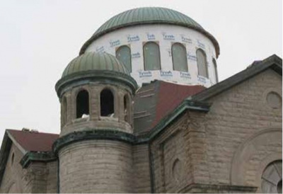
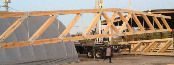
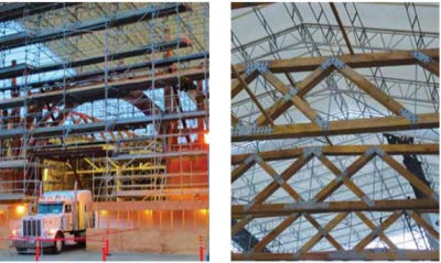
Byzantine-Style Church Reborn
Building: All Saint’s Church, Stuart, Iowa
Component manufacturer: Lumber Specialties, Dyersville, Iowa
Background: After All Saint’s Church burned in 1995, it wasn’t clear whether the structure would ever be rebuilt. But almost 14 years later, the historic southwest Iowa church rose again, thanks in part to wood and steel structural elements supplied by Lumber Specialties.
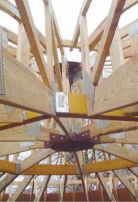
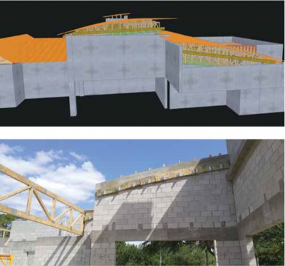
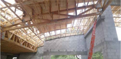
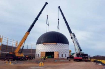
Project details: The challenge was how to frame a dome measuring 34 feet in diameter that would rest on a “drum” base. “The main dome is some 60 feet in the air. They didn’t want to stick [frame] it because of the cost to crane it, and then the time involved, too,” said Steve Kennedy, Lumber Specialties’ designer on the project. Having framers in the air for an extended amount of time wasn’t a safety risk anyone was eager to take, not to mention the very real possibility that the framing phase might hit during the brutally cold Iowa winter.
Steve included two unconventional elements to resist gravity and wind loads in order to match the geometry of the trusses to the dimensions of the dome. “We had to use AutoCAD to draw several circles and arcs (representing the curve of the dome) and then design the trusses to fit inside of them,” he said.
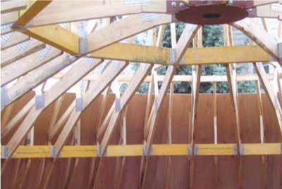
Steve came up with the concept to use steel compression and tension rings to tie the trusses into. Next, eight steeply pitched one-ply girder trusses were set and bolted to each of the center rings. These trusses come together to form the peak of the drum. In between each of the girder trusses was a short mono truss that extended to half the height of the drum. As shown in the pictures, two parallel rings of LVL beams allowed two sets of trusses to tie into the top and bottom rings. Kennedy noted that the hangers connecting the beams to the trusses required special detailing. “Every other hanger is a concealed flange,” he said.
2010
Building Community, Making Connections
Building: Habitat for Humanity Home, Charlotte, North Carolina
Component manufacturer: BCMC Build 2010
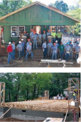
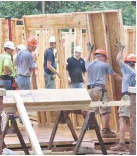
Background: No one will ever forget the first year of BCMC Build: rain, then mud, and a whole lot of camaraderie. Enough camaraderie, in fact, to change the tenor of the entire BCMC show. “The show has typically been very machine-focused. I don’t think that’s enough anymore, especially during a time when the industry wasn’t expanding a whole lot,” said Dan Holland, BCMC Build 2010 Chair. He thought a charitable event would unite people toward a common, positive goal. In essence, the Build more than lived up to the BCMC theme: Building Community, Making Connections.
Project details: A framing crew from Capital Structures drove over 900 miles towing a trailer full of tools. “They brought every tool you could possibly imagine from Arkansas to Charlotte,” Dan said. Four framers, plus Capital’s owner Steven Spradlin, coordinated each stage, calling out the next steps so other volunteers could prepare tools and materials.
The Habitat personnel learned a lot about how to use structural components and their benefits by observing how they were framed. “One of the site supervisors said they picked up two full days on the job by using components. We framed it in half the time, so they were very aware of the advantages,” said Jerry Vulgaris.
Dan believes the idea he had one morning driving to work in late 2009 had a large influence on the culture of BCMC. “I think probably a lasting one,” he said. Indeed, BCMC Build ultimately built seven homes for deserving families before transitioning into a national initiative focused on connecting component manufacturers with charity build projects throughout the year.
2012
A House of Epic Proportions
Building: 30,000 square foot single-family home, Stevens Point, Wisconsin
Component manufacturer: Blenker Building Systems, Amherst, Wisconsin
Background: The completion of this home was four years in the making. Blenker Building Systems (BBS) was invited to participate in the bid process for the project three years prior. “We actually knew the owner who wanted to build the house; he owns and operates a local business,” said BBS president Jason Blenker.
“This project was unusual in that, at the time of the bid, only about 30 percent of the drawings were done,” said Jason. “It was a design-build project almost from the start.”
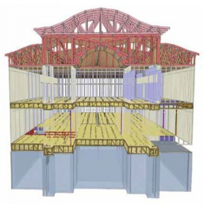
Project details: The “It was similar to some of the commercial jobs we’ve done in the past when we’ve been brought in by the contractor to help improve the design of the connections and ascertain the structural needs based on the architectural drawings,” said Jason. “Our designers had the opportunity to think outside the box on multiple occasions.”
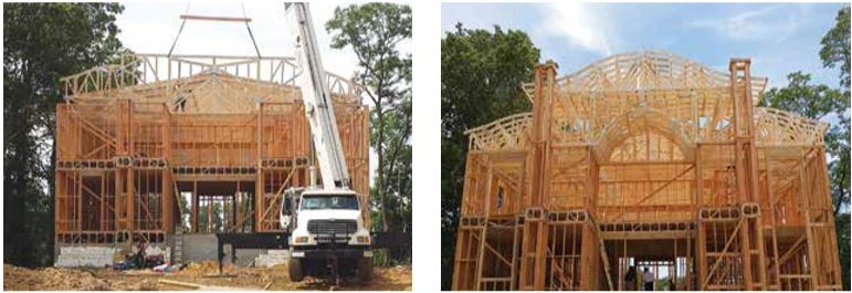
BBS also runs a turn-key operation. Not only can they contribute to the design, they also build and install the entire structure, including floor, wall, and roof components. Due to the size of the project, BBS had to start manufacturing and installing components long before they knew what the whole house would finally look like. Jason said, “We received initial figures in September, and by October we were already manufacturing some of the components.”
“One difficulty was having enough space for all the pieces inside our manufacturing facility, particularly the round pieces,” he said. “With an intricate project like this, we build the rooms in our facility to make sure everything fits, and then dismantle it and take it to the jobsite.”
What was the best part of the project? Jason said, “It was the uniqueness of the project and the opportunity it gave all of us to be creative.”
2013
Timber Trusses with a Tight Turn-Around
Building: Pier 29, San Francisco, California
Component manufacturer: Building Products Plus, Houston, Texas
Background: Around 1:50 pm on June 20, 2012, a spark from a welder’s work fell on a pile of dry wood and started a four-alarm fire that caused significant damage to the historic bulk work of Pier 29. The timing couldn’t have been worse, as the fire destroyed the roof and a large portion of the façade of the building, which was to be the home of the 2013 America’s Cup competition. The City of San Francisco was contractually obligated to provide the building for the race and suddenly found itself in its own race against time to rebuild the structure in a few short months.
Project details: In order to pull it off, the city had to appease many different interests, from historical preservationists to community activists to race organizers; re-engineer the building structure based on practically hundred-year-old drawings and schematics; and do so in an impossible timeframe. Enter Eric Lincoln and Building Products Plus Company, based in Houston, Texas, a leading producer of large-scale timber trusses and beams.
In total, Building Products Plus had to design six different truss layouts and manufacture 15 trusses. Eight of the trusses were 70-feet long with a top chord pitch so slight, it rose no more than two feet over the entire length of the truss. “The most challenging truss was the 58-foot, parallel chord girder truss, which carried the load of several other trusses,” said Chris Newhouse, P.E., the lead designer on the project for Building Products Plus. “The reaction loads on the truss at the bearing points averaged 22,000 pounds, so we ended up having to clad the top and bottom chords with a solid piece of half-inch steel that had to be cut into three lengths for shipping and then welded back together and affixed to the truss chords at the jobsite.”
Manufacturing these enormous trusses (some weighed in excess of 10,000 pounds) was not without its logistical challenges. “We had to create all the timber used in the trusses ourselves,” said Eric. “Most of it was 38-foot 10x10s and 10x12s that needed to be No. 1 and kiln dried to 19 percent.” In other words, when the contract was signed, the trees used in the project were still growing in a forest.
2014
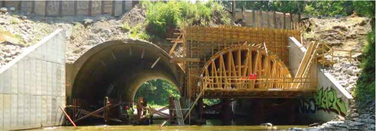
Barrel Trusses Show Perfect Form
Building: Route 5 Bridge, Fairview, Pennsylvania
Component manufacturer: Cussewago Truss LLC, Cambridge Springs, Pennsylvania
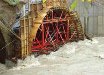
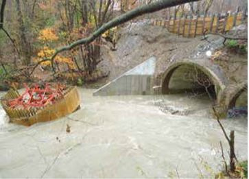
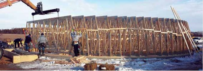
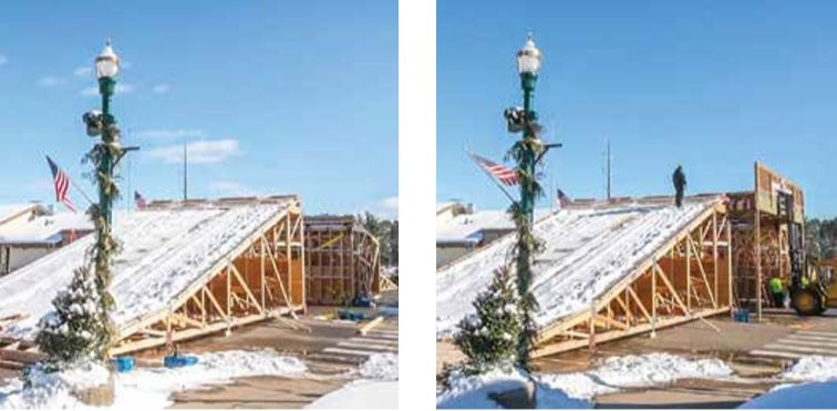
Background: About a mile inland from Lake Erie, Route 5 crosses Walnut Creek. The Pennsylvania Department of Transportation approved lengthening the tunnels by eight feet to make future widening of the road surface possible. Initially, the concrete formwork was made out of heavy-gauge steel that weighed over 17,000 pounds. On October 31, before the concrete could be poured, Superstorm Sandy’s torrential rains caused Walnut Creek to swell rapidly. The strong current pulled the steel structure away from the tunnel and carried it down the river, ruining it beyond use (top row photos below). State officials hoped there was a better way to finish the project.
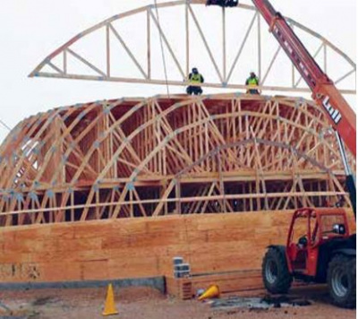
Project details: “It was an interesting challenge trying to design each segment so the top chord profile matched as closely as possible,” said Brian Otto, the project designer. When state officials got the cost estimates, they were blown away. Not only was Cussewago’s bid almost half the cost of the steel structure, it promised to be lighter and easier to install.
Most of the structure would have anywhere from 18 to 24 inches of concrete poured on top of it, but there were sections along the outer edges that had as much as nine yards of concrete poured on top. Brian designed the trusses to withstand 800 pounds per square foot. “Because of the application, we turned the wind and snow loading off in the software and calculated it as a uniform dead load,” said Brian. “The load duration was relatively brief as the weight of the concrete dissipates as it cures.”
Each truss was designed to be part of a four-ply girder, which would be fastened together in the field. Overall, the formwork structure needed to be 28 feet deep, so it required 14 four-ply girders spaced two feet on center. The top and bottom chords of each truss were constructed using Southern Yellow Pine MSR 2400, and the webs were constructed of SPF No. 2. Each single-ply truss weighed in at a hefty 500 pounds, making each girder an even ton.
2015
Jewish Synagogue with a Twist
Building: Spruce Street Shul, Lakewood, New Jersey
Component manufacturer: Woodhaven Lumber, Lakewood, New Jersey
Background: Per Jewish religious customs, electricity, and therefore speaker systems, cannot be used at given times, so this synagogue needed to have especially good acoustics. Initial plans for the 4,680 square foot shul included a 49 foot by 48 foot main hall with no intermediate supports. The design incorporated a curved ceiling, to help sound travel, but the roof above had to support large mechanical units. In addition, the customer wanted the building to have added curb appeal, so the front of the Spruce Street Shul called for a detailed parapet.
Project details: The customer approached Woodhaven Lumber with the project and a bit of a challenge. “With a straight face, the customer said, ‘Put a truss there (in the main hall). I bet you can’t do this,’” said Jesus Betanzos, lead designer.
First, Jesus tackled the design. Fortunately, Woodhaven Lumber already had a good relationship with the architect, who supplied CAD files of the design. Jesus took the CAD files and transposed them into the truss design software. He designed the curved ceiling of the main hall so it could withstand the additional load from mechanical units overhead and included the parapet in the truss design using three arches and two radiuses.
Then the truss plant had to make those truss designs a reality. “Everyone in the shop was mad at me that week,” joked Jesus. Woodhaven didn’t have automated tables, which made the job especially challenging, but the staff in the truss plant were up to the demanding, set-ups for the roof and floor trusses for the project, which included curved trusses for the main hall that spanned 51 feet. “I couldn’t have done it without the guys in the shop. They really came through,” said Jesus.
2016
Hurricane-Proof, West Coast Style Home
Building: Single-family home, West Palm Beach, Florida
Component manufacturer: A-1 Roof Trusses, Fort Pierce, Florida
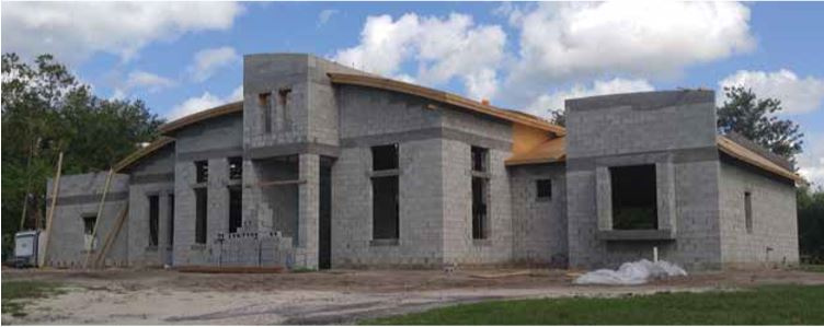
Background: Dennis Rainho of YRA Design said his customer wanted “a house that doesn’t look like your typical south Florida house.” Inspired by styles in Colorado and California, the homeowner asked Dennis to give a “contemporary look” to a concrete-block house, designed to withstand Florida’s hurricane-force winds.
Project details: The construction methods typically used in West Coast housing—timber, laminated beams, steel—are generally more expensive than wood, Dennis said. Those materials can make curves easier but, “if we do soft curves,” Dennis told the homeowner, “we can probably do this using trusses.” Trusses could meet all the requirements of the project: they were within the owner’s budget, they could support a curved exterior roof as well as interior ceilings with faux beams for a striking, exposed-structure look, and the web member spacing could be designed to accommodate the large ducts needed for air conditioning.
“It was definitely very challenging,” says Ryan Spencer, the truss designer in A-1 Roof Trusses’ custom division who worked with Dennis. The designs called for a truss that could be adjusted during installation. “We did flat trusses, all the same depth,” Ryan said, set at different heights against the walls and supporting girders. With the girders at fixed heights and the trusses staggered, framers could “adjust the bearing height to form the curve in the field.” Each truss was trimmable so that framers could fit it into the hanger and make adjustments as needed along the way. The design gave framers “the most flexibility as they were building to make sure the elevations were correct.”
“It was all about trying to get the heights right,” he said.
2017
A Really Sweet Truss Dome
Building: Jim’s Apple Barn, Jordan, Minnesota
Component manufacturer: Manion Lumber & Truss, Pillager, Minnesota
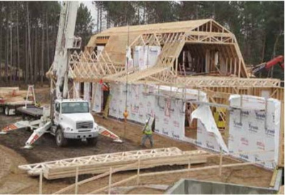
Background: When Jim’s Apple Barn, the largest candy store in Minnesota, wanted to expand by way of adding a confection-filled planetarium to the end of a blazing yellow barn already bursting with sweets, it had a difficult time finding a truss company willing to take on the project. “We were the only ones that said yes,” said Trevor Ebinger, sales rep for Manion Lumber & Truss. “It was quite an undertaking.”
Project details: Mike Seeley, project designer, set almost 1,000 different planes in the truss design software to build a truly round building dome. His plans included only two each of 94 different trusses. With a two-piece piggy back, the truss assembly stood 32 feet high. Originally, Manion planned for the trusses to be installed in place, on top of the walls. “The contractor was like, ‘Oh, please! I really don’t want to build this up in the air!’ So we had to go back to the drawing board and rethink,” said Trevor.
Mike completed the truss, purlin, and sheathing design, ensuring vertical webbing within the trusses transferred all the weight evenly out to the edge of the structure, and then he passed everything along to the company supplying the walls. It was a good doublecheck that all the load paths were correct and that the trusses, fully assembled on the ground, could be lifted into place atop the walls. “There was a lot of engineering that went into just making sure it would lift!” said Trevor.
The dome wasn’t the only aspect of the structure that made truss production difficult. The project was also big. “At the center of the building, the trusses themselves are 31 feet tall, and our tables are only capable of doing 14 feet at a time,” Mike said. “So these trusses had to be three sections. You have over 100 pieces to make each truss. So it’s a lot.”
The entire roof system was nearly 32,000 pounds, Mike recalled, and it was assembled with only a handful of clarifying questions from the jobsite crew. “When they lifted it up,” said Mike, “it didn’t make a sound!”
2018
A Truss Bridge Like No Other
Building: American Birkebeiner Bridge, Hayward, Wisconsin
Component manufacturer: Trussworks, Inc., Hayward, Wisconsin
Background: How’s this for the design project’s loading conditions? A minimum of one foot of snow dead load, a five-ton live load, and accommodation for roughly 13,000 individuals moving over it. It also needs to span 30 feet in two sections, needs to be 16 feet high and 24 feet wide, and it must accommodate ramps at either end, as well as pedestrian stair access. To top it off, it has to be mobile and capable of being constructed and deconstructed in only a few hours.
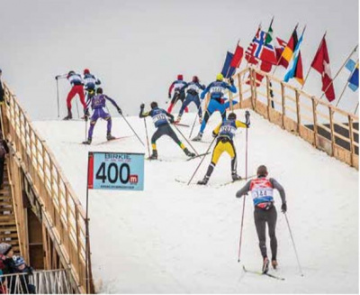
Project details: “We originally designed the bridge to span 30 feet to go over two lanes of traffic and then added a second 30 foot span with a 10 foot median the next year,” said Mike Walters, the lead designer on the project. “We also had to design essentially three truss configurations, which made up the ramps racers used to get up and over the bridge. We also had to incorporate into the design a way to span over a permanent water fountain on the ramp leading up onto the bridge. We ran a 2/12 pitch for the ramp they have to climb, which takes about 100 feet to get up to the 16-foot height.” Overall, the bridge is 198 feet long and weighs close to 50,000 pounds.
“The biggest challenge from a design perspective was accommodating the five-ton snow groomer they have to drive over the bridge once they’ve loaded it with snow a foot thick,” said Mike. Each 30-foot span was constructed of five 1/2-inch by 24-inch glulam beams spaced eight feet apart. Three sections were used to give the bridge its 24-foot width. The spans had a 3-1/8-inch treated glulam deck. In total, the bridge required 15,500 screws to fasten it all together.
“Another interesting challenge was coming up with a design that could be quickly assembled and then disassembled,” said Mike. They broke the design into 24 unique items that needed to be assembled on site. The bridge typically requires 17 flatbed semi-trucks to haul around.
2019
BIM Delivers on Big Boston Project
Building: Clippership Warf, Boston, Massachusetts
Component manufacturer: Shelter Systems Limited, Westminster, Maryland
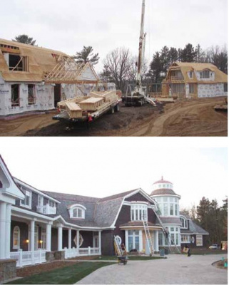
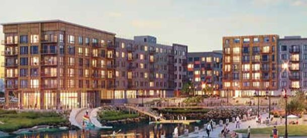
Background: According to the Boston Business Journal, the East Boston waterfront has witnessed a number of luxury housing developments go up over recent years but none are quite as ambitious as Clippership Wharf. Made up of four separate buildings sitting on 12 acres of waterfront property, the project encompasses 284 apartments and 194 condominiums surrounding a central courtyard with a 270-degree view of the downtown Boston skyline.
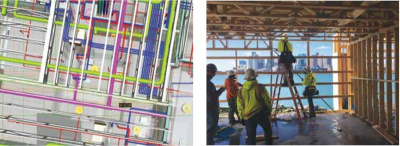
Project details: In total, Shelter supplied 9,250 floor trusses, 1,580 roof trusses, 30 Smart Component portal frames, 115 component headers and 245 componentized parapets. The most amazing part? “Installation went very smoothly and we didn’t have a single repair or call back related to an MEP conflict,” reported Shelter’s technical team leader Tony Acampa. The key to that success started with the developer’s requirement that all contractors fully commit to using the building information modeling (BIM) process before anything was constructed on the jobsite. Tony said, “we try our best to avoid MEP clashes on every job we do. But if we hadn’t done the BIM work on the front of this job, there were aspects that easily could have been a disaster.”
While all that coordination and collaboration through BIM took a considerable amount of time, it is hard to argue with the results. Shelter didn’t have a call back or repair due to a clash with MEP on the entire project. Installation of all the structural elements went very smoothly, from the floor trusses to the Smart Component portal frames, and BIM had a lot to do with it. “We avoided all the inevitable field repairs and time delays you would typically see on a project of this size,” said Tony.
“I worked closely with Jim Bassett at ECI (the framer) throughout the installation process. It was easy communication back and forth because everyone’s expectations were met,” said Tony. He pointed out that everyone, including ECI, were committed to the BIM process. One of the most impactful consequences was that the framers followed the plans exactly. The framers couldn’t (and didn’t) decide on the jobsite to modify anything, trusting that all the conflicts had been worked out in advance.
We Need Your Help!
SBC Magazine would like to continue its practice of highlighting the amazing work component manufacturers (CMs) are accomplishing for their customers across the country. As you can see from this sampling, some of these projects relied on exceptional engineering, design skill, and experience. Other projects relied on meticulous production logistics and coordination, and still others simply took the courage to say “yes” to a customer when they came and asked for a solution to a tricky problem.
CMs do this kind of thing every day, week after week, year after year. There are likely hundreds of projects just like these that provided exceptional value over the past decade that did not make it into our pages. If you complete a project where you are proud of what your sales, design, production, transportation, and/or installation teams accomplished, we want to know about it and share their success with the rest of the industry.
There is a wealth of tips, best practices, and business approaches that can be learned through each project. Help us share these valuable insights with the rest of industry. If you have a project you want us to consider publishing in a future issue, contact us at editor@sbcmag.info.