Unbearable Conditions
Unbearable Conditions

When a truss is designed, a check is made in the design software to assure the bearing capacity of the truss is sufficient. This article will look at ways to address insufficient bearing capacity, but first it’s necessary to look at the mechanics that go into determining bearing capacity.
Why Bearing Capacity Is So Important
As with any organic material, there are microscopic voids within a material’s cells that make up its structure. Wood is no different. Lumber is partially made up of soft strands, which creates its “grain.” While the grain may be strong as a column (i.e., load carried parallel to the grain), or “with the grain,” direction, load applied perpendicular to the grain is weaker and can be “crushed” under load. Yet, loading perpendicular to grain is a very common occurrence in a building. The photo at left shows what happens to lumber being crushed when loaded perpendicular to the grain. The bottom chord of a truss and the top plate of a wall are two prime examples of lumber needed to resist load applied perpendicular to grain. Accounting for crushing is always a check that the software performs during truss design.
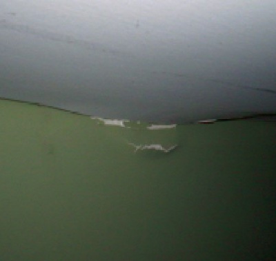
Ceiling bow due to lumber crushing
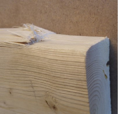
An example of lumber crushing perpendicular to grain
The straw-like fibers that create the grain structure in the lumber, run the length of each piece of lumber. As already mentioned, the direction of the grain affects its resistance to being crushed by load. Because of this lumber trait, the design values for lumber differ for load applied parallel versus load applied perpendicular to the direction of the grain. For example, if you pushed on the end of a tight pack of straws, there will be very little “give” by the straws. However, if you pushed on the side of the straws, or perpendicular to the grain direction, it will be much easier to crush the pack.
Lumber performs following this simple concept. In fact, lumber can withstand approximately three times more load in the parallel direction than it can in the perpendicular direction. This difference can be used to increase bearing capacity, which will be covered below. Examples of lumber compression parallel and perpendicular to grain design values are shown in the table below, which reference Tables 4A and 4B in the 2018 NDS Supplement. Since Spruce-Pine-Fir (SDF) and Southern Pine (SP) are two key species used in trusses and walls, these two species are listed here. All lumber species are included in the NDS.
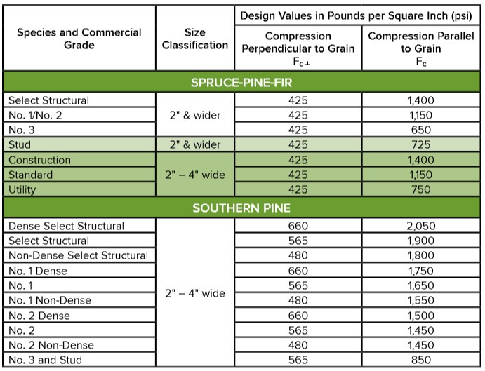
Reference Design Values for Compression
As with all engineered use lumber design properties, compression design values are dependent on lumber species and grade. When reviewing the NDS Supplement for various species of lumber, there is often no difference between grades of a species for compression perpendicular to the grain values. The table above shows this to be true for SPF and not true for SP. This is because SP has a unique, higher density characteristic where higher density provides for greater compression perpendicular to grain resistance.
On the other hand, machine graded lumber differs from visually graded lumber in that compression perpendicular to grain changes with modulus of elasticity and species. For example, SPF has three compression perpendicular to grain values.
How Bearing Capacity Is Determined
The reference lumber design value is just one data point in determining the bearing capacity of a piece of lumber. Several adjustments need to be made to the reference design value in order to determine the bearing capacity of lumber. Adjustments to that capacity depend on the moisture content of the lumber, the use of the lumber, lumber treatment through small incisions referred to as incising, and the size and location of each of the bearings.
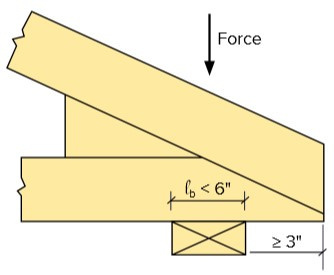
Illustration of Bearing Area Factor
The following factors are used to determine bearing capacity:
- Wet Service Factor (CM) - Sawn lumber that undergoes moisture cycles will have a reduction in bearing capacity as it is know that lumber is weaker when it is wet.
- Incising Factor (Ci) – Similar to the wet service factor, lumber that is incised to be treated with preservative is weaker.
- Temperature Factor (Ct) - Lumber that is exposed to high temperature dries out, which has an effect on the resistance properties of lumber.
- Bearing Area Factor (Cb) - The final lumber factor consideration for calculating bearing capacity is an adjustment that allows an increase in allowable resistance. If the bearing length is less than 6″ and the edge of the location of the bearing is greater than or equal to 3″ from the end of the support, this increase applies. This concept is illustrated at right.
In a previous article on this topic by SBCA a table showing the reactions possible for different species of wood was created. This helpful table (below) can give a preliminary idea of what the allowable bearing load is.
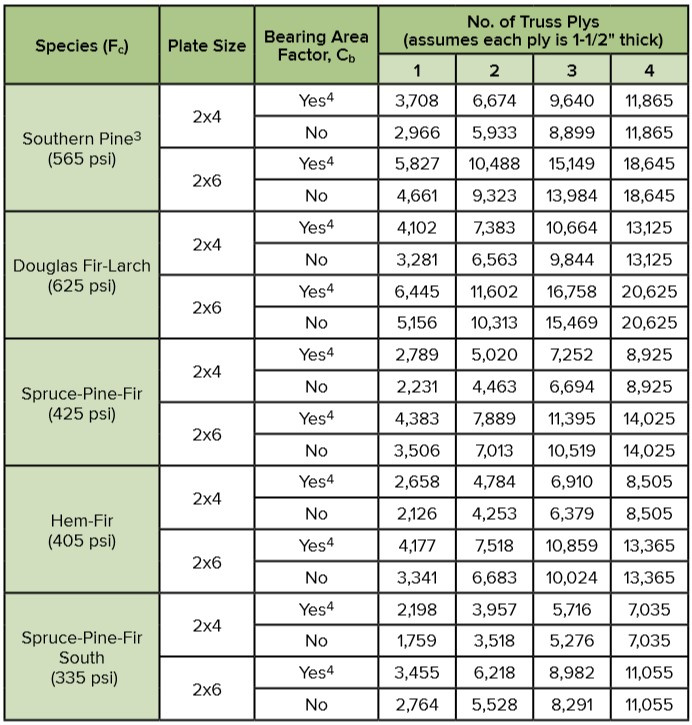
Maximum Truss Reaction (lbs) Based on Allowable Compression Stress Perpendicular to Grain of the Lumber Plate
Compression Perpendicular to Grain Design Considerations
The main point to take away is that not all lumber is created equal, and compression perpendicular to grain design considerations and factors are complicated. On the one hand, the truss design software will easily deal with the truss bearing capacity. The greater challenge is determining what bearing condition the truss rests upon.
- One case is a girder truss, be it a single-ply or multi-ply truss, where the top plate is typically a consistent dimension along the length of the wall. The girder truss transfers a high amount of load into the bearing. This generally requires the bearing to have additional capacity. Girder trusses with multiple plies are favorable, in this situation, as the greater the number of plies means more surface area for the girder to transfer its reaction to the bearing below.
- Another case is based on trusses having the unique ability to be designed with long spans making them desirable for areas where a large open room, free of internal support, is desired. These long-span trusses convey higher loads due to the tributary area served. Although it is possible for a truss to have a long clear span, even in high roof load areas, interpretation of construction documents are necessary to understand designed support conditions of the truss.

Solutions for Increasing Bearing Capacity
This may seem like more detail than is needed to cover a seemingly simple concept. That said, when the various factors and footnotes are removed, bearing capacity boils down to two simple concepts: surface area and resistance to crushing.
There are many ways to address the issue of insufficient bearing area. Which method you or your designer chooses depends greatly on the ability to adjust the design. The designer may be able to specify a leg-down truss for one job, but need to use bearing blocks for another. Below are a few examples of solutions that can improve the bearing capacity:
Upgrading Lumber
Upgrading the lumber is one way that bearing capacity can be increased. While this is not true for many species of visually graded lumber due to limited range of perpendicular to grain lumber design properties, it is true for SP and Machine Stress Rated (MSR) lumber. Switching species may also be an option as SP typically has a greater capacity.
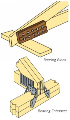
Bearing Blocks & Enhancers
If bearing area is inadequate and changing lumber type, species or grade are not options, bearing blocks and bearing enhancers are two options to increase bearing capacity. Bearing blocks, attached at the bearing location, will increase the bearing area without increasing the load applied to the area. Bearing enhancers are metal plates that are attached to the truss and top plate. These devices come with stated capacities, which help to ensure that the insufficient bearing area is corrected.
Leg Bearing
If a raised heel truss is used, the designer can design the truss such that the leg of the truss is used for bearing. The lumber used in the leg has compression parallel to grain capacity, which as mentioned previously, has three times the capacity of compression perpendicular to grain.
One item to note when doing this is that section 7.3.9.2 of TPI 1-2014 has a requirement that the design bearing capacity cannot exceed 75 percent of the allowable bearing capacity when both the bearing and the support are oriented parallel to the grain. In other words, if the allowable bearing capacity is 1,000 psi the design capacity can only be 750 psi. If, in this case, the design capacity is 1,000 psi, a 20 gauge metal plate must be installed between the leg and the vertical member supporting the leg. This prevents the two pieces of lumber from “brooming,” which occurs when the lumber splits apart resulting in movement of the bearing location.
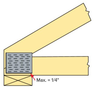
Flush Plate
The final potential improvement is to add a plate flush to the bottom of the chord at the bearing location as shown in the illustration below. This option exists for 2x trusses bearing on the 1.5″ face and the plates are installed no more than 1/4″ from the lumber edge. By plating near the bottom of the chord, in this manner, the bearing capacity can be increased by 18 percent.
This may not be possible, depending on the truss configuration and will only improve the bearing capacity of the truss and not the support.
Bottom Line
Bearing capacity is one piece of the puzzle that both building designers and truss designers must consider. It is very important, because it can change the entire truss design. So much time and effort is spent making sure the truss carries the load path efficiently and economically from the roof to the foundation. To not consider how the truss will transfer loads at bearing very early in the design process can cause multiple truss redesigns, which can become expensive quickly.