Get a Leg Up on Leg-Down Trusses
Get a Leg Up on Leg-Down Trusses
Leg-down trusses require special design considerations that typical heel-bearing trusses do not, so it is important for truss and building designers to pay close attention to a few key elements.
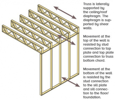
Figure 1.
A leg-down or leg-thru to bearing condition occurs when the web of a truss extends to a bearing surface that is below the bottom chord plane of the truss. This condition occurs most often when the truss designer is asked to provide trusses with varying ceiling heights while maintaining the same bearing elevation. Proprietary truss design software typically allows a leg-down condition to be modeled; however, there are a few design considerations that the software may not handle automatically. Understanding these limitations will ensure that these types of trusses are designed correctly.
Conventional light-frame (2x4 or 2x6 wood frame) walls require lateral support at the bottom and top of the wall to resist out-of-plane loads applied perpendicular to the wall (see figure 1). This support is typically provided prescriptively by attaching the bottom of the wall to the foundation or floor and the top of the wall to a ceiling or roof diaphragm.
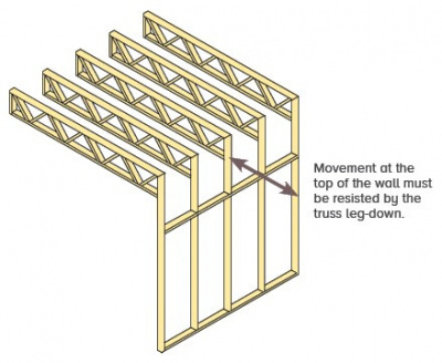
Figure 2.
With a leg-down application, the top of the wall is below the ceiling and roof diaphragm and the vertical web of the truss must be designed to laterally support the wall if no other lateral support exists (see figure 2).
To illustrate further, the left image in the figure (figure 3 at left) shows the typical condition where the wall extends to the bottom chord of the truss. The wall acts as a vertical beam with supports at the foundation and the top of the wall where the bottom chord of the truss sits on it.
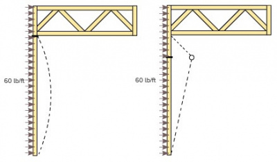
Figure 3.
When wind load is applied against the face of the wall, the dashed line illustrates the exaggerated displacement over the length of the wall. When a leg-down condition occurs, as depicted in the illustration at right, continuity of the wall is interrupted and there is a theoretical hinge (i.e., continuity break) at the top of the wall. An instability will occur unless the leg-down is capable of supporting the top of the wall.
Most software applications have an option to automatically apply wind load to the vertical truss member in a leg-down application. However, the portion of the wind load applied to the wall, which must be resisted by the truss, must be added by the truss designer as a horizontal concentrated load at the bottom of the vertical truss member.
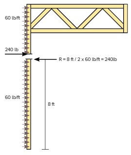
Figure 4.
For example, the figure (figure 4 at right) shows a leg-down truss bearing on top of an 8-foot wall. Assume that the 60 lb/ft (i.e., plf) wind load on the wall is equal to the wind load applied to the end vertical for the software load case. If the leg-down supports the wall, the portion of the wind load applied to the wall that must be resisted by the leg of the truss is calculated as follows:
- The tributary length of the wall load going to the truss is 4 feet (8 ft ÷ 2)
- This 4 feet is multiplied times the wind load of 60 plf.
- 4 ft x 60 lb/ft = 240 lbs
This load is applied as a horizontal concentrated load to the bottom of the vertical truss member. Note that since wind load can act either toward or away from the wall, the truss must be analyzed with the condition where the 240 lb concentrated load acts inward as well as the condition where the 240 lb force acts outward.
If the wall is an interior wall, building codes require the wall be able to resist a minimum lateral load applied to the face of the wall. For example, IBC 2015 section 1607.14 requires 5 psf for interior walls that exceed 6 feet in height. Using the same example as above for a leg-down truss occurring at interior walls should therefore be designed to resist the applicable portion of this load as follows:
- For a 10-foot interior wall, the tributary length of the wall load going to the truss is 5 feet (10 ft ÷ 2)
- This 5 feet is multiplied times the leaning load that is applied to interior walls of 5 psf times 2 feet on center for 10 plf.
- 3. 5 ft x 10 lb/ft = 50 lbs
It is recommended that the designer clarify additional leg-down load assumptions by adding a note to the truss design drawing. For example, “A 240-lb wind load has been applied to the bottom of the leg-down to account for lateral support of the wall below.”
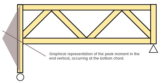
A second consideration when designing a leg-down truss concerns the modeling of the leg-down bearing condition. The bearing condition at the bottom of the leg-down should always be a horizontal roller, to permit lateral displacement of the leg-down. If a pin is modeled, the concentrated load will go directly into the bearing support rather than be resisted by the leg-down.
In other words, the leg-down should behave as a beam with a cantilever extension, with a peak moment occurring at the bottom chord similar to the image below. The bearing at the opposite end of the truss will need to be modeled as a pin or the truss model has inadequate lateral restraint and will be unstable. If both ends of the truss have leg-downs, the truss needs to be analyzed twice with the bearing conditions alternated to design each leg-down properly while keeping the truss stable.
Finally, the connection of the leg-down to the top of the wall should be designed to transfer the horizontal wall reaction in addition to any uplift from the truss that occurs.
In summary, the leg-down configuration typically creates a situation where the leg-down must be designed to laterally support a wall below. To account for wall load on the leg-down, a point load should be placed at the bottom of the leg-down. The bearing at the leg-down should be modeled as a horizontal roller to allow the leg-down to displace laterally under the applied load. This ensures the leg-down is designed for the forces that exist when the leg-down acts as a lateral support for the wall.