BIM Ensures Big Project Is a Huge Success
BIM Ensures Big Project Is a Huge Success
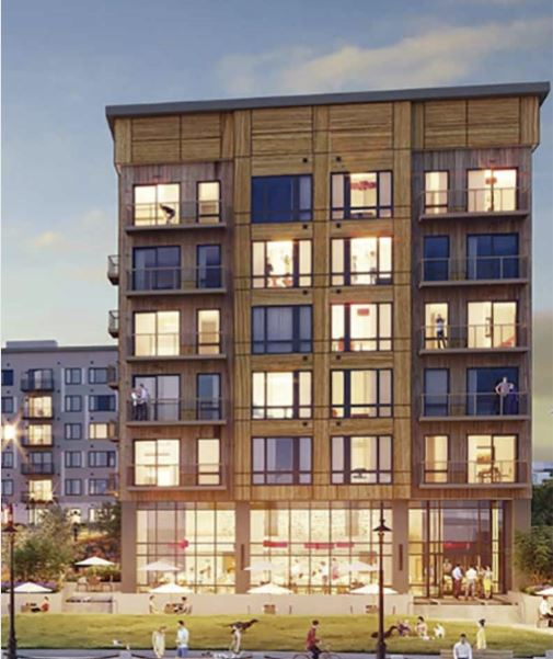
When the Australian real estate giant Lendlease decided to get into the U.S. market, they adopted the old adage “go big or go home.” One of their first projects was 432 Park Avenue in New York City, which is currently the tallest residential building in the western hemisphere. While not quite so high profile, one of Lendlease’s first endeavors in a joint enterprise with First State Super, an enormous pension fund in Australia, was the Clippership Wharf project on the Boston Harbor.
According to the Boston Business Journal, the East Boston waterfront has witnessed a number of luxury housing developments go up over recent years, but none are quite as ambitious as Clippership Wharf. Made up of four separate buildings sitting on 12 acres of waterfront property on which the project encompasses 284 apartments and 194 condominiums surrounding a central courtyard with a 270-degree view of the downtown Boston skyline.

The land it sits on was originally at the heart of Boston’s seafood industrial complex and needed significant investment to create the man-made property on which the buildings are constructed. The final price tag for the completed development will exceed $270 million. While the fourth building is still currently under construction, the condos in Slip 65, the first building completed, sold out in eight weeks with price tags ranging from $500,000 to $1.5 million.
All of this is to say that Lendlease has a lot riding on the success of this venture and was motivated from the beginning to bring together an A-team of contractors to get the project built on time and on budget. To that end, they hired East Coast Interiors (ECI) out of Warwick, Rhode Island, as their turnkey framing contractor. ECI had framed a number of large, multifamily projects in Boston. ECI, in turn, hired Shelter Systems (Shelter) in Westminster, Maryland, to supply the floor and roof trusses, as well as Smart Components portal frames, component headers, and parapets for the entire project. Additionally, they hired a Canadian firm, AmeriCan Structures, to supply the wall panels.
 “When we got involved with this project in late 2016, it was only the second time we had ever worked with ECI,” says Tony Acampa, the lead designer on the project. “Due to its success, we’re now engaged in several other projects with them.”
In total, Shelter supplied 9,250 floor trusses, 1,580 roof trusses, 30 Smart Components portal frames, 115 component headers and 245 componentized parapets. The most amazing part? “Installation went very smoothly and we didn’t have a single repair or call back related to an MEP conflict,” Tony reports. The key to that success started with Lendlease’s requirement that all contractors fully commit to using the building information modeling (BIM) process before anything was constructed on the jobsite. Tony adds, “we try our best to avoid MEP clashes on every job we do, but if we hadn’t done the BIM work on the front end of this job, there were aspects that easily could have been a disaster.”
To appreciate the enormity of that last paragraph, it’s important to look at the BIM process in which Tony participated (below), Shelter’s approach to designing the project (digital edition page 25), and all that went into ensuring a smooth installation (digital edition page 30).
Appreciating the Value of BIM
When Shelter Systems (Shelter) in Westminster, Maryland, was brought in by turnkey framer East Coast Interiors (ECI) to supply the floor and roof trusses, Smart Components portal frames, component headers and parapets for the Clippership Wharf luxury apartments and condos on the Boston harbor, they agreed to fully participate in the building information modeling (BIM) process. The real estate developer, Lendlease, had made BIM a requirement of all the contractors involved in the project.
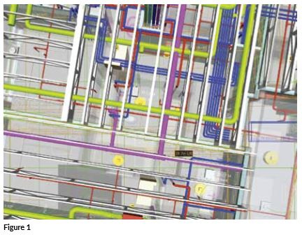 BIM uses powerful software to incorporate the designs and layouts of all the contactors involved in a construction project into a virtual, 3D output of the building. Everyone involved can then collaborate in real-time to resolve conflicts between various structural elements and mechanical, electrical, and plumbing (MEP) infrastructure (Figure 1).
“I had never worked with BIM before this project, so there was certainly a learning curve at the start,” says Tony Acampa, the lead truss designer for the project. “It was also a significant time commitment over the life of the project.” Tony attended two-and-a-half hour BIM sessions twice a week for over eight months as the first three buildings were constructed. However, Tony believes the sessions were time well spent.
“Most of the other trades were familiar working with BIM and so I gained an appreciation for the process from them as we went along,” he says. “I also learned a lot about their approach to design and the requirements and limitations they faced as individual trades, which will make me a better designer in the long run.” The other trades also gained valuable perspective on truss design and capabilities from Tony as they worked to solve conflicts between the structural elements and the MEP designs.
Prior to each session, every contractor would upload their designs and schematics to a digital exchange server. A specialist at Lendlease would then launch the BIM session and all the contractors would log into the virtual space to view the 3D rendering. This process did not always go smoothly, of course.
“The success of BIM absolutely relies on every contractor doing their job and ensuring their design files are correct. Early on, I had some of my x, y, and z coordinates wrong and that made the truss alignment off in the model,” says Tony. “A couple of times I needed to recheck a few settings and re-upload my design files so they would display correctly in the model.”
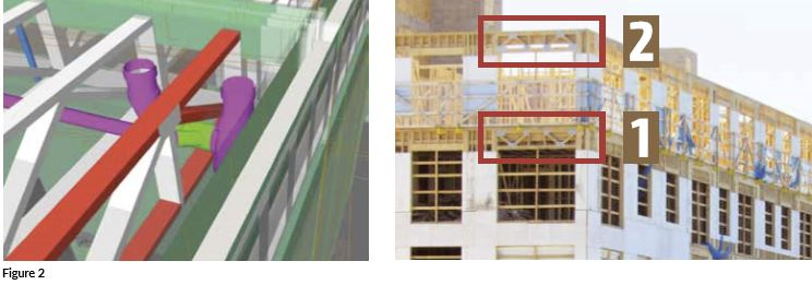 Once everything was uploaded correctly, they would navigate through the 3D BIM model and look for conflicts (Figure 2). They would then collaborate on how best to resolve each conflict. “We would discuss the easiest solution to implement. Sometimes it would be as simple as moving a plumbing trap over a couple of inches,” says Tony.
However, one of the biggest struggles was the fact that the BIM specialist was an IT and software professional; he didn’t have a construction background. His job was to document every conflict identified by BIM and ensure there was a resolution to it. So, for instance, if the BIM model indicated a truss web and a pipe overlapped by a half inch, either Tony or the plumber had to go in and adjust their plans to eliminate that clash (see image above).
“The cool part was that they all understood the structure was the most important part and so they were really good at working with me to find solutions that didn’t require many changes to my designs,” says Tony. However, there were a few cases where Tony needed to make a change to his design. “In one case, there was an exhaust pipe that needed to extrude from the building right in the middle of a component header I had designed. The easiest solution was for me to alter the web pattern to create an opening for the pipe.” In the image at right, the webs in the component header on the third floor (Box 1) were altered compared to the header on the fourth floor (Box 2).
While all that coordination and collaboration through BIM took a considerable amount of time, it is hard to argue with the results. Shelter didn’t have a call back or repair due to a clash with MEP on the entire project. Installation of all the structural elements went very smoothly, from the floor trusses to the Smart Components portal frames, and BIM had a lot to do with it. “We avoided all the inevitable field repairs and time delays you would typically see on a project of this size,” says Tony.
Managing Load Path Through Component Design
 Turnkey framer East Coast Interiors (ECI) contracted with Shelter Systems (Shelter) to manufacture an interesting combination of structural framing elements for Australian real estate developer Lendlease’s high profile Clippership Wharf project on the Boston Harbor. Shelter designed and manufactured 1,580 roof trusses and 9,250 floor trusses needed for the project. However, since Shelter doesn’t manufacture wall panels, ECI contracted with AmeriCan Structure to supply the walls.
Interestingly, this didn’t mean Shelter wasn’t intimately involved in the design and manufacture of some of the wall elements. For instance, Shelter designed and manufactured 30 Smart Components portal frames for three of the four buildings that make up Clippership Wharf (to learn more about Smart Components and how Shelter added them to their product offering see “Selling Smarter” in the November 2016 issue of SBC Magazine).
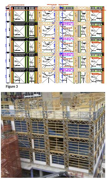
Bob Dayhoff, director of technical operations at Shelter, works hard to build relationships with design professionals in their markets and explain their benefits in hopes they will specify Smart Components. Clippership Wharf was a perfect fit for this type of framing product. “With these buildings being right on the water across from the Boston skyline, there was a strong interest in having as much of the exterior be glass as possible,” says Tony Acampa, the lead truss designer on the project. The windows extend from floor to ceiling on every unit. To resist all the shear loads involved, the Smart Components portal frames (Figure 3 and image at right) became an elegant answer.
The floor to ceiling windows also created an opportunity for Shelter to design and manufacture 115 component headers for use between many of the floors. “Those headers needed to be physically incorporated into AmeriCan’s wall panels in their Canadian facility,” says Tony, “but we couldn’t ship them directly to their plant” since they needed drivers with dual citizenship and special import/export permits. Instead, they delivered the headers to the jobsite in Boston. Once on the jobsite, AmeriCan sent their drivers to pick up the headers and take them back to Canada. There they were built into the wall panels and shipped back across the border to the jobsite.
“This was the first time we had ever worked with AmeriCan, but they were amazing,” says Tony. “The coordination with their panel designer was very straightforward and we had a lot of good conversation. We will definitely work with them again, given the chance.”
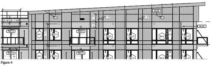 To produce the gently sloping roofline for building three (Figure 4), Shelter also supplied 245 componentized parapets (Figure 5). Being a type 3A building, the roof trusses were constructed of southern yellow pine, but the parapets were made entirely of FRT lumber.
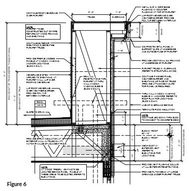
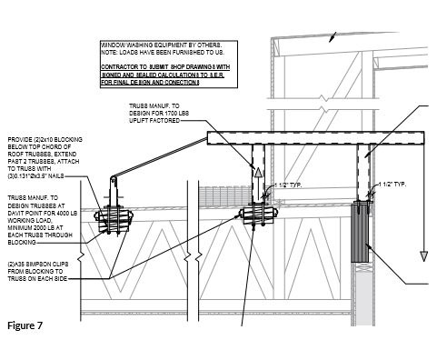
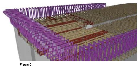 The parapets themselves were not overly challenging to design (Figure 6), but incorporated into the parapets were several davits (i.e., miniature cranes) that hoist and lower the platforms used by window washers. Lendlease knew the owners of these luxury apartments would expect their views of downtown Boston to remain pristine, and that means the windows need to be cleaned regularly. “The existence of these davits required certain roof trusses and the Smart Components to resist an incredible amount of lateral uplift and gravity loads (Figure 7). All of the red girder trusses in Figure 5 corresponded to where the davits were affixed to the roof.
 “The biggest benefits of the BIM process (digital edition page 22) for me came into play in this roof area,” says Tony. “If we hadn’t coordinated ahead of time where all the MEP was going to go in relation to the roof trusses and we ran into a conflict on the jobsite, it would not have been easy to fix. The girder trusses in particular couldn’t have been moved very easily.”
Proactive Approach Yields a Smooth Installation
After all the effort that went into the BIM coordination between the various trades, the payoff was realized during the installation process. “Installation was a breeze,” says Tony Acampa, lead designer on the Clippership Wharf project for Shelter Systems (Shelter).
“I worked closely with Jim Bassett at ECI throughout the installation process. It was easy communication back and forth because everyone’s expectations were met,” says Tony. He points out that everyone, including ECI, were committed to the BIM process. One of the most impactful consequences was that the ECI framers followed the plans exactly. The framer couldn’t (and didn’t) decide on the jobsite to modify anything, trusting that all the conflicts had been worked out in advance.
 “If Jim ever came across something, he wouldn’t take it upon himself to implement a change in the field, he would immediately call me,” says Tony. “We would agree to a course of action and move on. He wouldn’t even shift a truss an inch because he knew it might actually cause a conflict.” As a consequence, there weren’t any significant delays on the jobsite during the framing process.
From Shelter’s perspective, there were several positive outcomes based on their approach to this project:
- They contributed in a significant way to a very high-profile development in downtown Boston.
- They collaborated successfully with a number of big-name players in multifamily construction.
- They established a good working relationship with a large, turnkey framer in their market.
- They made a connection with another wall panel manufacturer who could provide a strategic partnership in the future.
- One of their lead designers learned a great deal about how BIM works and what it can offer to the component manufacturing industry.
- They designed, manufactured, and sold to one customer a total of 9,250 floor trusses, 1,580 roof trusses, 30 Smart Components portal frames, 115 component headers, and 245 componentized parapets.
Given these outcomes, would Shelter do it all again? “Absolutely!” says Tony. “We’ve already signed on to another one of these types of projects.”